3D Mechanical Part Image to Technical Drawing Conversion
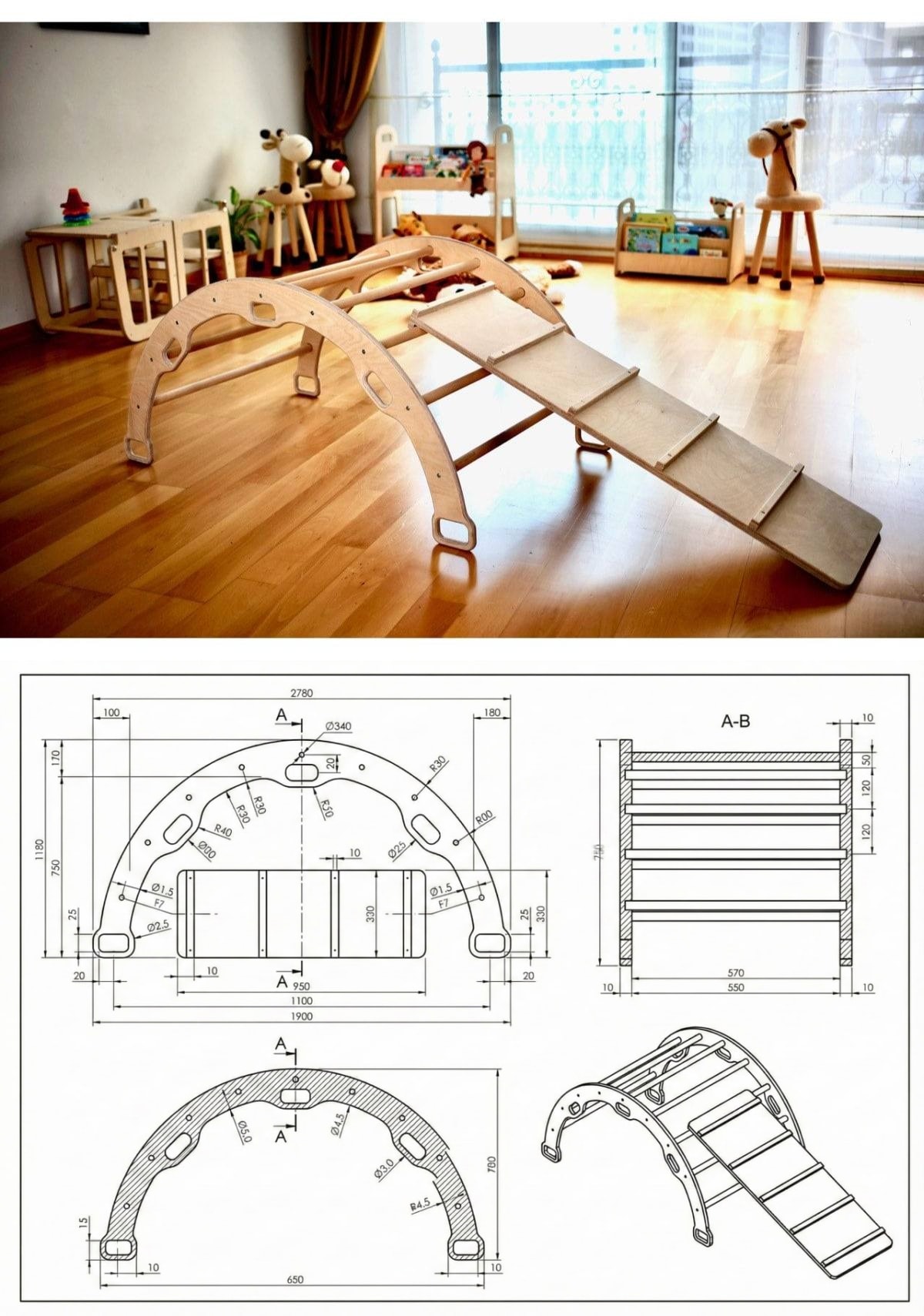
Convert a 3D rendered image of a mechanical part into a detailed technical drawing sheet. The sheet includes fully dimensioned orthographic views, a sectional view with internal geometry, and an isometric reference view, all following ISO mechanical drafting standards.
Example outputs
Prompt template
- Format
- Json
- Inputs
- reference_image (image) · Required
- Outputs
- result (image)
{
  "task": "image_to_image",
  "input_image": "3d_render_of_mechanical_part.png",
  "prompt": "Reference scale: the outer diameter of the flange is exactly 360 mm. Mechanical engineering drawing sheet with three separate drawings of the same part placed in clearly separated rectangular areas. Drawing 1: fully dimensioned orthographic views (front, top, side) with precise numeric measurements in millimeters, diameter symbols, radius annotations, hole count notation and center lines. Drawing 2: sectional view taken through the center axis of the part, showing internal geometry with proper section hatching and wall thickness clearly visible. Drawing 3: isometric reference view of the part without any dimensions, used only for spatial understanding. ISO mechanical drafting standard, consistent line weights, monochrome black lines on white background, manufacturing-ready technical documentation, no perspective distortion.",
  "negative_prompt": "single combined drawing, merged views, artistic rendering, perspective view, realistic lighting, shadows, textures, colors, gradients, sketch style, hand drawn look, missing dimensions, decorative presentation",
  "settings": {
    "model": "sdxl",
    "sampler": "DPM++ 2M Karras",
    "steps": 45,
    "cfg_scale": 6,
    "denoising_strength": 0.45,
    "resolution": {
      "width": 1024,
      "height": 1024
    }
  },
  "output_expectation": "one technical drawing sheet containing three clearly separated drawings: dimensioned orthographic views, a centered sectional view, and an undimensioned isometric reference, suitable for manufacturing reference"
}
What you'll create
Separate rectangular areas organize the monochrome engineering-style sheet. A 360 mm flange diameter supplies the stated reference scale, with consistent line weights and section hatching.
Generation settings
Advanced settings
- Negative prompt
- single combined drawing, merged views, artistic rendering, perspective view, realistic lighting, shadows, textures, colors, gradients, sketch style, hand drawn look, missing dimensions, decorative presentation
- Steps
- 45
- CFG scale
- 6
Frequently asked questions
Does the isometric reference carry dimensions?
No. It is explicitly for spatial understanding, while dimensions belong to the orthographic views.
Comments
Tried this prompt? Share what you made, compare results, or ask a question